← Back to projects
RC beam analysis and design
Welcome
ACI 318
STRUCTURAL ENGINEERING TOOLKIT

RC beam analysis and design

Educational and professional workstation for the rigorous step-by-step analysis and design of reinforced concrete beams at ultimate flexural and shear limit states per ACI 318.

Analysis of Reinforced Concrete Beams
Compliant with ACI 318 Building Code
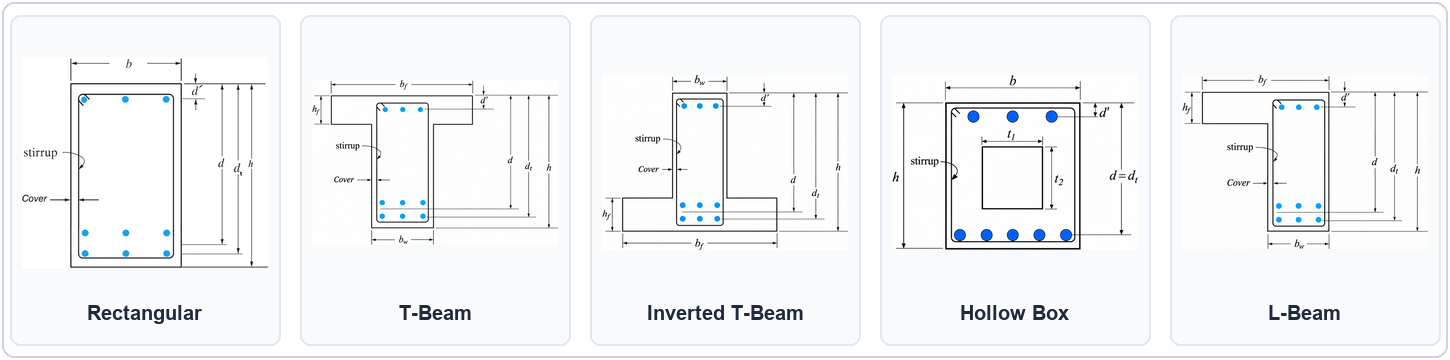
5 SUPPORTED GEOMETRIES SINGLY & DOUBLY REINFORCED FLEXURAL & SHEAR ANALYSIS
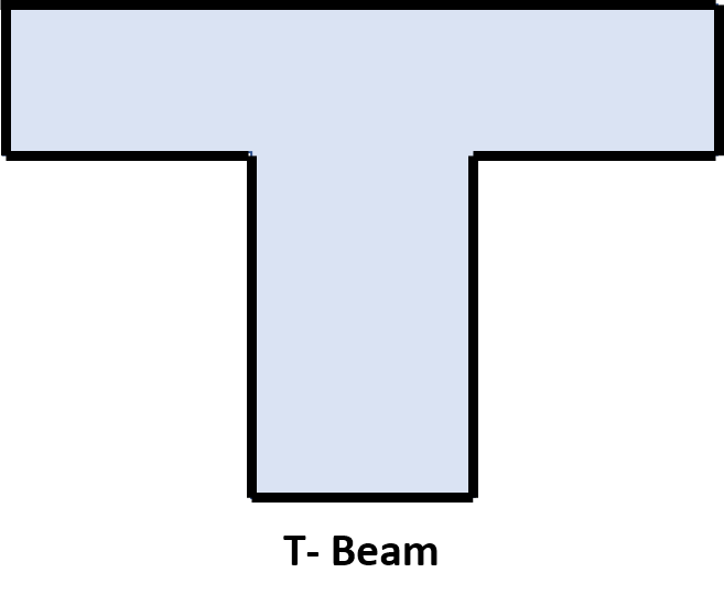
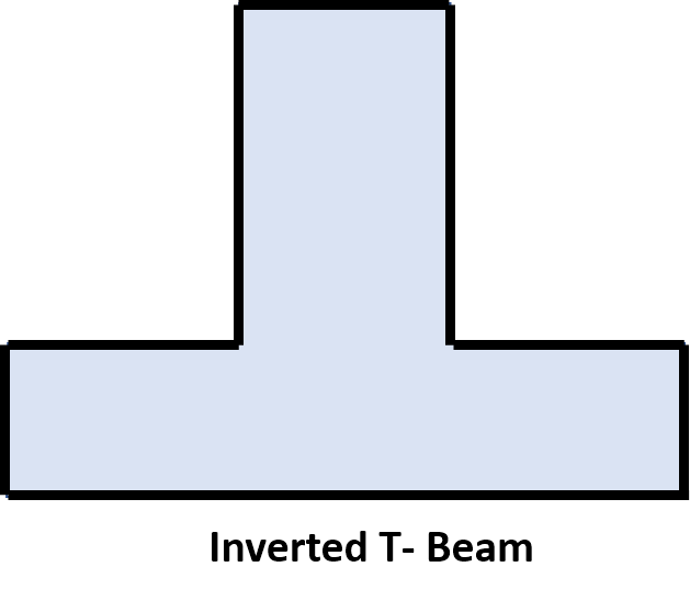
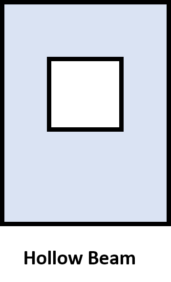
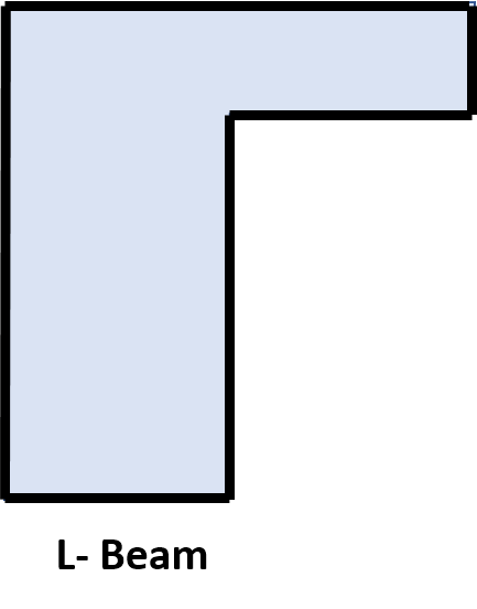
Supported Beam Cross-Sections: Rectangular, T-Beam, Inverted T-Beam, Hollow Box, L-Beam
Comprehensive Cross-Section Capabilities: Rectangular, T-Beam, Inverted-T, Hollow Box & L-Beam
Rigorous strain compatibility, nominal & design flexural capacity (φMn), and shear strength (φVn) per ACI 318

Structural Engineering Modules

Select the desired calculation workflow compliant with ACI 318-19

Flexural Analysis

φMn
ACI 318-19 5 Cross-Sections Singly & Doubly
c (N.A.) 0.85f'c a = β₁c Cc Ts φMn
Rigorous strain-compatibility analysis and Whitney rectangular stress block computation for ultimate flexural bending strength.
  • ✓ 5 Shapes: Rectangular, T-Beam, Inverted-T, Hollow Box, L-Beam
  • ✓ Steel Detailing: Singly & Doubly reinforced with compression yield check
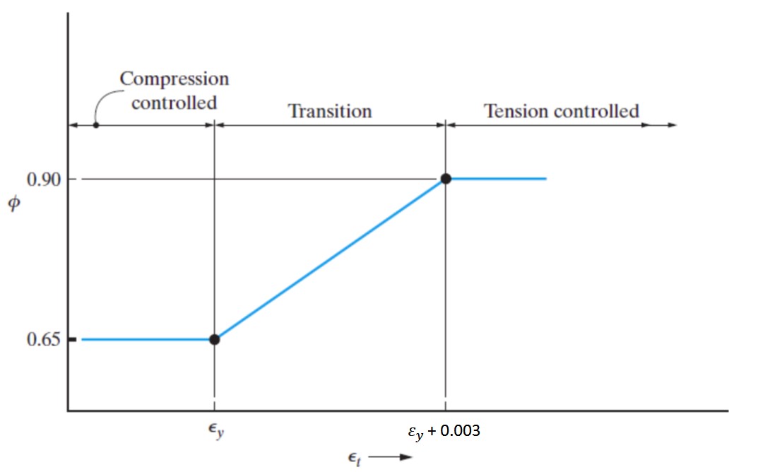
  • ✓ Ductility Checks: Net tensile strain εt, φ factor (0.65–0.90), bar spacing
  • ✓ Interactive Detailing: Live cross-section canvas & full MathJax derivation

Shear Strength Analysis

φVn
ACI 318-19 Rectangular Beams Stirrup Detailing
Vu 45° Shear Crack spacing (s) φVn = φ(Vc+Vs) ≥ Vu
Concrete shear contribution (Vc), transverse steel stirrup capacity (Vs), and complete ACI 318 code spacing limit checks.
  • ✓ Concrete Shear Vc: Simplified ACI formula 0.17λ√f'c bw d
  • ✓ Stirrup Capacity Vs: Vertical legs Av fyt d / s with code limits
  • ✓ Section Verification: Maximum Vs ≤ 0.66√f'c bw d criteria check
  • ✓ Spacing Detailing: Minimum Av,min check & maximum s_max envelope

Select Cross-Section Geometry
Rectangle
Rectangle
T-Beam
T- Beam
Inverted T-Beam
Inverted T-Beam
Hollow Beam
Hollow Beam
L-Beam
L- Beam

Select Reinforcement Configuration
Tension Steel Only
Double Reinforced

Flexural Section Workstation

Configure geometry, materials, and reinforcement detailing
ACI 318-19
📐 Section Geometry
Direct Effective Depth (d) given?
Direct Extreme Layer Depth (dt) given?
Direct Compression Steel Depth (d') given?
mm
mm
mm
🧱 Material Properties
MPa
MPa
GPa
⚡ Tension Steel Reinforcement (As)
mm
As= 1521.14 mm²
⚡ Compression Steel Reinforcement (As')
mm
As'= 628.57 mm²
🔗 Shear Stirrup Detailing
mm
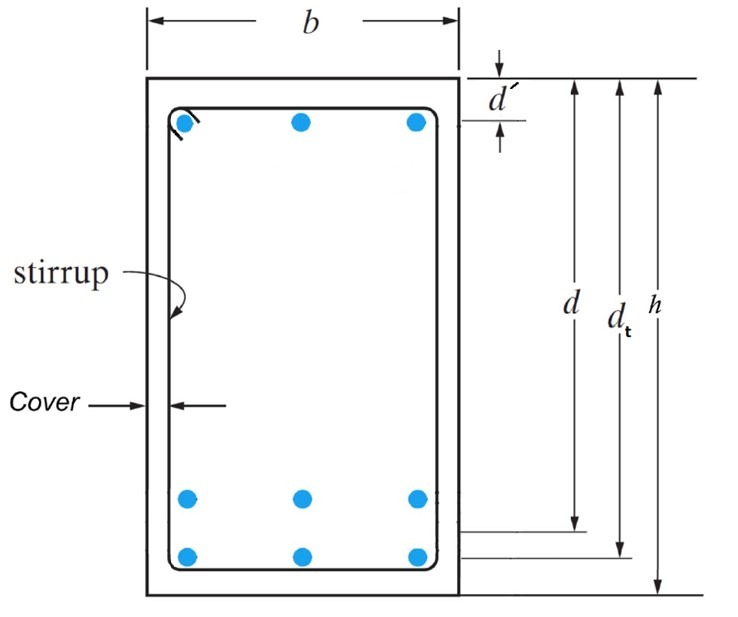
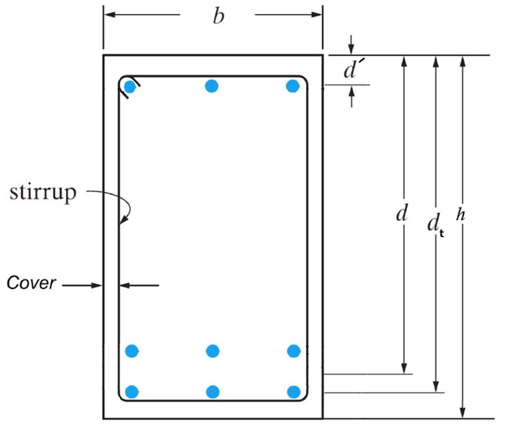
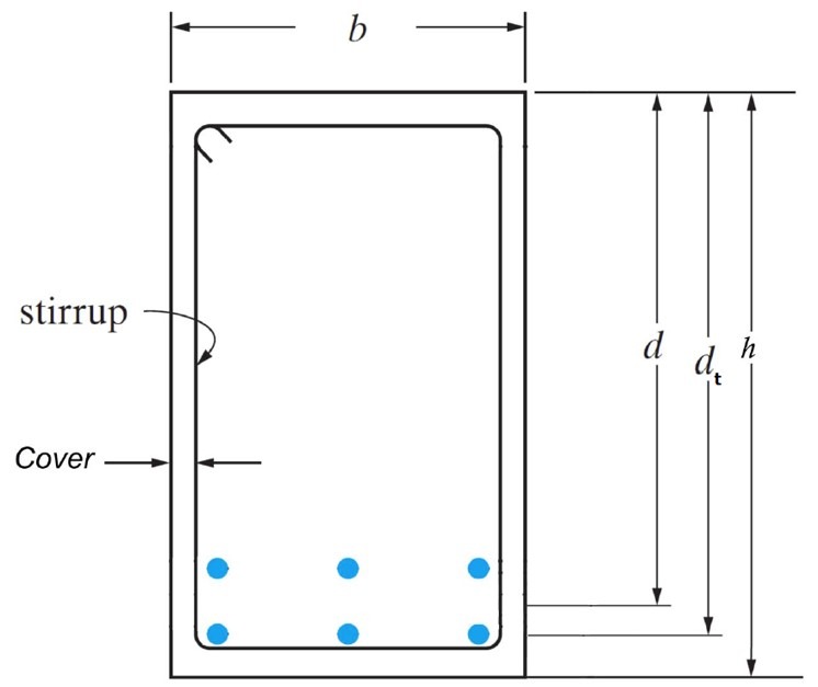
📐 Geometric Dimension Reference
Beam parameters
🔍 Cross-Section Detailing

Analysis Summary & Design Checks

Flexural capacity and ACI 318 code verification
Design Flexural Strength (φMn)
135.98 kN·m
Factored ultimate moment capacity per ACI 318-19
📏 Part 1: Bar Spacing Check
Tension Steel: Can bars be placed in one layer?
Yes
Actual Clear Spacing: 56 mm
>
Minimum Required: 25 mm
Compression Steel: Can bars be placed in one layer?
Yes
Actual Clear Spacing: 60 mm
>
Minimum Required: 25 mm
⚙️ Part 2: Section Parameters & Assumptions
Assume: fs = fy fs' = fy φ = 0.90
Section Behavior: Rectangular
Effective Depth (d): 315.5 mm
Compression Steel Depth (d'): 60 mm
Extreme Layer Depth (dt): 339 mm
Tension Steel Area (As): 1521.14 mm²
Compression Steel Area (As'): 628.57 mm²
Stress Block Depth (a): 105.01 mm
Whitney Factor (β1): 0.85
Neutral Axis Depth (c): 123.54 mm
🔬 Strain Verification
Tension Steel Strain (εs): 0.00466 > 0.00210 (εy)
Fs is equal to Fy
Compression Steel Strain (εs'): 0.00154 < 0.00210 (εy)
Fs' is not equal to Fy, new a must be found
Extreme Layer Strain (εt): 0.00428 < 0.00510
The beam is not in Tension controlled zone, new φ must be found
Recalculated Equilibrium Parameters:
New a:118.70 mm
New c:139.65 mm
Fs' / Fs:342.22 MPa
New φ:0.832

Example:

divider

Flexural Analysis With ACI 318

Section and Material Properties:

h=400 mm
b=200 mm
Cover=40 mm
fc' =21 MPa
fy =420 MPa
Es=200 GPa
Tension Reinforcement:
4 Φ22 mm in 2 layers
As=1521.14 mm²
Compression Reinforcement:
2 Φ20 mm in 1 layer
As'=628.57 mm²
Shear Reinforcement(Stirrup):
Φ10 mm
divider

Solution:

Part 1: Pre Calculation

$$\text{Min. Layer Spacing is largest of } \begin{bmatrix} 25\text{ mm} \\ \phi_{bar} \\ \frac{4}{3} * \text{Max. Aggregate Size} \end{bmatrix}$$
Hint: $\frac{4}{3}$ of max aggregate size has been neglected in this program
Layer Spacing = 25 mm
Beam Depth Dimensions
$$d = h - \text{cover} - \phi_{stirrup} - \frac{\text{No. of layers}}{2} \times \phi_{bar} - \frac{\text{No. of layers} - 1}{2} \times \text{Layer Spacing}$$
d = 315.5 mm
$$d_t = h - \text{cover} - \phi_{stirrup} - \frac{1}{2} \times \phi_{bar}$$
dt = 339 mm
$$d' = \text{cover} + \phi_{stirrup} + \frac{1}{2} \times \phi'_{bar}$$
d' = 60 mm

Part 2: Check the Section Data

In this section the given values will be compared with the limitation according to the selected Code, Since this program is for educational purpose even if the given data are beyond the limitation the analysis still will be done

Tension Bar Spacing:

According to the code the bar spacing must be larger or equal to min bar spacing otherwise the bar arrangement must be changed.
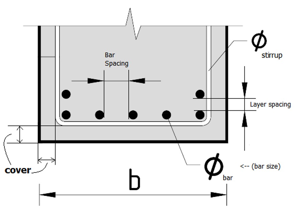
Tension Bar Spacing
$$\text{Bar Spacing} = \frac{b - (2 * \text{Cover}) - (2 * \phi_{stirrup}) - (\text{no. of bars} * \phi_{bar})}{(\text{no. of bars} - 1)}$$
Bar Spacing = 56 mm
$$\text{min. bar spacing is largest of } \begin{bmatrix} 25\text{ mm} \\ \phi_{bar} \\ \frac{4}{3} * \text{Max. Aggregate Size} \end{bmatrix}$$
Min. Bar Spacing = 25 mm
Since bar spacing is greater than min bar spacing the bar arrangement is OK

Compression Bar Spacing:

According to the code the bar spacing must be larger or equal to min bar spacing otherwise the bar arrangement must be changed.
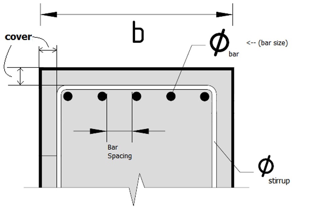
Compression Bar Spacing
$$\text{Bar Spacing} = \frac{b - (2 * \text{Cover}) - (2 * \phi_{stirrup}) - (\text{no. of bars} * \phi_{bar})}{(\text{no. of bars} - 1)}$$
Bar Spacing = 60 mm
$$\text{min. bar spacing is largest of } \begin{bmatrix} 25\text{ mm} \\ \phi_{bar} \\ \frac{4}{3} * \text{Max. Aggregate Size} \end{bmatrix}$$
Min. Bar Spacing = 25 mm
Since bar spacing is greater than min bar spacing the bar arrangement is OK

As Minimum

According to the code provided tension steel less than the min steel area is not permitted

$$A_{s,min} = \max\left( \frac{0.25\sqrt{f'_c}}{f_y} b d, \;\; \frac{1.4}{f_y} b d \right)$$
As,min = 210.33 mm²
Provided As (1521.14 mm²) ≥ As,min (210.33 mm²) [OK]

As Maximum

According to the code provided tension steel more than the maximum steel area is not recommended

As,max = 2450.80 mm²
Provided As (1521.14 mm²) ≤ As,max (2450.80 mm²) [OK]

Part 3: Analysis

In this section we will find the ultimate flexural moment capacity of the beam, i.e the maximum allowable applied moment

Step 1: Assumptions

φ = 0.90
fs = fy
fs' = fy

Step 2: Find a and c

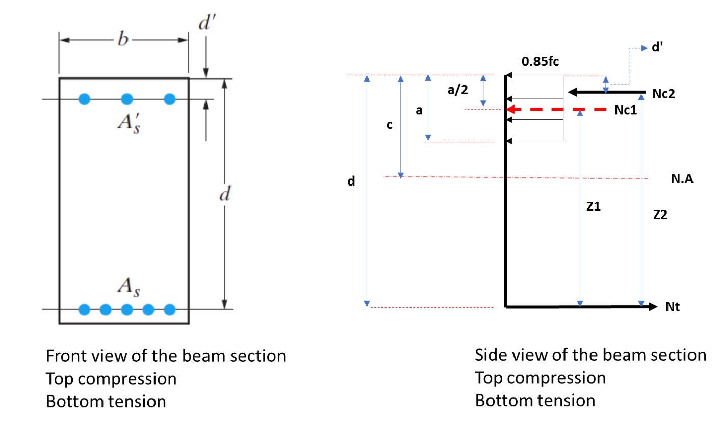
Stress Block Diagram
a = 105.01 mm
$$a = \beta_1 \cdot c \implies c = \frac{a}{\beta_1}$$ $$\beta_1 = 0.85$$
c = 123.54 mm

Step 3: Check the Assumptions of step 1
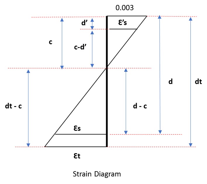
Strain Diagram
$$\varepsilon_y = \frac{f_y}{E_s * 1000}$$
εy = 0.0021
$$\frac{\varepsilon_s}{d - c} = \frac{0.003}{c} \implies \varepsilon_s = \frac{0.003 (d - c)}{c}$$
εs = 0.00466
Since εs ≥ εy then fs = fy
$$\frac{\varepsilon_s'}{c - d'} = \frac{0.003}{c} \implies \varepsilon_s' = \frac{0.003 (c - d')}{c}$$
εs' = 0.00154
Since εs' < εy then fs' is not equal to fy, new a must be found
$$\frac{\varepsilon_t}{d_t - c} = \frac{0.003}{c} \implies \varepsilon_t = \frac{0.003 (d_t - c)}{c}$$
εt = 0.00428
Since εt < εy + 0.003, the beam is not in Tension controlled zone, new φ must be found

Step 4: Find new a and c

Value of the two roots are:
a1 = 118.70 mm
a2 = -45.39 mm
we will choose New a = 118.70 mm
New c = 139.65 mm
Find New εs' and Fs':
$$\frac{\text{New } \varepsilon_s'}{\text{New } c - d'} = \frac{0.003}{\text{New } c}$$
New εs' = 0.00171
$$F_s' = \varepsilon_s' * E_s * 1000$$
New fs' = 342.21574 MPa
Re-check εs:
$$\frac{\text{New } \varepsilon_s}{d - \text{New } c} = \frac{0.003}{\text{New } c}$$
New εs = 0.00378
since new εs > εy then fs = fy
Re-check φ:
$$\frac{\text{New } \varepsilon_t}{d_t - \text{New } c} = \frac{0.003}{\text{New } c}$$
New εt = 0.00428
Since New εt ≥ εy + 0.003, the beam is in tension controlled zone
Since εt > εy and εt < εy + 0.003 the beam is in transition zone
φ = 0.83167

Step 5: Find Ultimate Flexural Capacity

Mu= 135984540 N·mm / 10⁶
Mu= 135.98 kN·m
divider

Notation and Abbreviations:

$a$= depth of equivalent rectangular stress block
$A_s$= area of longitudinal tension reinforcement
$A_s'$= area of compression reinforcement
$A_{sf}$= steel area required to balance the flange overhang
$A_{sw}$= steel area required to balance the web compression
$A_{s,min}$= minimum area of flexural reinforcement
$A_{s,balance}$= balanced area of flexural reinforcement at balanced failure i.e., the tension reinforcement is just reaching its yield strain, at the same time the extreme concrete compression fiber is reaching the maximum useable compression strain 0.003
$b$= width of compression face or total flange width
$b_w$= width of web (stem)
$h_f$= thickness of flange
$c$= distance from extreme compression fiber to neutral axis
$c_c$= clear cover of reinforcement or layer spacing
$d$= distance from extreme compression fiber to centroid of longitudinal tension reinforcement
$d'$= distance from extreme compression fiber to centroid of longitudinal compression reinforcement
$d_t$= distance from extreme compression fiber to centroid of extreme layer of longitudinal tension reinforcement
$E_s$= modulus of elasticity of reinforcement and structural steel
$f'_c$= specified compressive strength of concrete
$f_y$= specified yield strength for longitudinal reinforcement
$f_s$= stress in the tension reinforcement
$f_s'$= stress in the compression reinforcement
$h$= overall height, or depth of member
$M_u$= factored moment at section
$N_c$= total internal compressive force
$N_{c1}$= internal compressive force from concrete resistance (flange or rectangular block)
$N_{c2}$= internal compressive force from steel or web concrete resistance
$N_t$= total internal tensile force
$N_{t1}$= internal tensile force from bottom tension reinforcement
$N_{t2}$= internal tensile force from top reinforcement when $c < d'$ (top steel in tension)
$f_{s2}$= tensile stress in top reinforcement when $c < d'$
$\beta_1$= factor relating depth of equivalent rectangular compressive stress block to depth of neutral axis
$\varepsilon_{cu}$= maximum strain at extreme concrete compression fiber "0.003"
$\varepsilon_s$= tensile strain in center of longitudinal tension reinforcement at nominal strength
$\varepsilon_s'$= compressive strain in center of longitudinal compression reinforcement at nominal strength
$\varepsilon_{s2}$= tensile strain in top reinforcement when $c < d'$ (top steel in tension)
$\varepsilon_t$= net tensile strain in extreme layer of longitudinal tension reinforcement at nominal strength
$\phi$= strength reduction factor
$Z$= internal lever arm between resultant compressive and tensile forces ($d - a/2$)
$Z_1, Z_2$= internal lever arms for component forces in doubly reinforced or flanged sections

Shear Analysis Workstation

Rectangular section shear capacity evaluation per ACI 318
📐 Cross-Section Dimensions
mm
Direct Effective Depth (d) given?
mm
mm
🧱 Material Strengths
MPa
MPa
🔗 Stirrup (Shear) Reinforcement
mm
legs
mm
⚡ Longitudinal Tension Bars (Section Detailing)
bars
mm
🔍 Shear Cross-Section

Shear Analysis Summary

Design shear strength and ACI 318 code limitations
Maximum Permitted Factored Shear (Vu)
388.55 kN
$$V_u = \phi V_n = \phi V_c + \phi V_s \quad (\phi = 0.75)$$
Concrete Capacity ($V_c$)
333.35 kN
φVc = 250.01 kN
Stirrups Capacity ($V_s$)
184.73 kN
φVs = 138.54 kN
🛡️ ACI 318 Code Provisions & Checks
Section Crushing Check ($V_s \le V_{s,max}$)
Web crushing limit: $V_{s,max} = \frac{2}{3}\sqrt{f'_c} b_w d = $ 1333.38 kN
Adequate
Stirrup Spacing Check ($s \le s_{max}$)
Maximum allowable spacing: $s_{max} = $ 420 mm
OK (300 ≤ 420 mm)
Minimum Shear Reinforcement ($A_v \ge A_{v,min}$)
Provided $A_v = $ 157.08 mm², Required $A_{v,min} = $ 112.50 mm²
Satisfied

Example:

divider

Shear Analysis of Rectangular Beam With ACI 318

Section and Material Properties:

bw = 450 mm
d = 840 mm
fc' = 28 MPa
fyt = 420 MPa
Stirrups: 2 legs Φ10 @ 300 mm
Tension Steel: 7 Φ22 mm
Cover: 40 mm

Step 1: Calculate Concrete Shear Strength ($V_c$)

According to ACI 318, for members subject to shear and flexure only (normalweight concrete, $\lambda = 1.0$):
$$V_c = \frac{\sqrt{f'_c} \, b_w \, d}{6}$$
$$V_c = \frac{\sqrt{28} \times 450 \times 840}{6} \times \frac{1}{10^3} = 333.345 \text{ kN}$$
$V_c = $ 333.345 kN

Step 2: Calculate Stirrups Area ($A_v$) & Steel Shear Strength ($V_s$)

For vertical stirrups with perpendicular spacing $s$:
$$A_v = n_{\text{legs}} \times \frac{\pi \, d_v^2}{4}$$
$$A_v = 2 \times \frac{\pi (10)^2}{4} = 157.08 \text{ mm}^2$$
$$V_s = \frac{A_v \, f_{yt} \, d}{s}$$
$$V_s = \frac{157.08 \times 420 \times 840}{300} \times \frac{1}{10^3} = 184.725 \text{ kN}$$
$V_s = $ 184.725 kN

Step 3: ACI 318 Code Checks & Limitations

1. Maximum Shear Strength Check (Web Crushing Limit):
ACI 318 limits $V_s \le \frac{2}{3}\sqrt{f'_c} \, b_w \, d$:
$$V_{s,max} = \frac{2}{3}\sqrt{28} \times 450 \times 840 \times \frac{1}{10^3} = 1333.38 \text{ kN}$$
Since $V_s \le V_{s,max}$ ($184.73 \text{ kN} \le 1333.38 \text{ kN}$), beam cross-section dimensions are ADEQUATE.
2. Maximum Stirrup Spacing ($s_{max}$):
Since $V_s \le \frac{1}{3}\sqrt{f'_c} \, b_w \, d$ ($184.73 \le 666.69\text{ kN}$):
$$s_{max} = \min\left(\frac{d}{2}, 600\text{ mm}\right) = \min(420, 600) = 420\text{ mm}$$
Since $s = 300\text{ mm} \le 420\text{ mm}$, stirrup spacing satisfies maximum code limit.
3. Minimum Shear Reinforcement ($A_{v,min}$):
ACI 318 specifies minimum area of stirrups per spacing $s$:
$$A_{v,min} = \max\left(0.062\sqrt{f'_c} \frac{b_w s}{f_{yt}}, \; \frac{0.35 b_w s}{f_{yt}}\right) = 112.50\text{ mm}^2$$
Since $A_v = 157.08\text{ mm}^2 \ge 112.50\text{ mm}^2$, minimum shear reinforcement is satisfied.

Step 4: Factored Shear Capacity & Maximum Permitted $V_u$

For shear strength design, the strength reduction factor is $\phi = 0.75$:
$$V_u = \phi V_n = \phi V_c + \phi V_s$$
$$\begin{aligned} V_u &= 0.75 \times 333.345 + 0.75 \times 184.725 \\[0.3em] &= 250.009 + 138.544 = 388.55 \text{ kN} \end{aligned}$$
Maximum Factored Shear Force Permitted on Member:
$V_u = 388.55\text{ kN}$

Shear Reinforcement Design Workstation

ACI 318-19 Web Reinforcement Synthesis & Detailing (CVLE372)
📐 Cross-Section Dimensions
mm
Direct Effective Depth (d) given?
mm
mm
📍 Critical Section Location
At d from support
Measure Vu at support face?
If OFF (default): ACI 318-19 §9.4.3.2 — critical section at d from support face.
🧱 Material Strengths
MPa
MPa
⚡ Factored Shear Demand / Loading
m
kN/m
🔗 Stirrup Specification
Auto Assumed
Specify Stirrups Manually?
If OFF, the design automatically assumes standard Φ10 double-leg stirrups.
mm
legs
⚡ Auto-Design Assumption: Standard Φ10 double-leg stirrups (Av = 157.1 mm²) will be assumed. If required spacing is congested (s < 75 mm), the design will automatically step up to Φ12 or 4-leg stirrups.
🔩 Longitudinal Tension Detailing (Visual)
bars
mm
🔍 Cross-Section Preview
📐 Beam Loading Diagram

Shear Design & Detailing Summary

ACI 318-19 Web Reinforcement Synthesis & Spacing Envelope
Design Web Reinforcement Specification:
Provide Φ10 mm (2 legs) @ 125 mm c/c
First stirrup placed at s/2 ≤ 50 mm from support face
📈 Shear Force Diagram (SFD) & Design Zones
ACI 318: Critical Section at d
📐 Beam Longitudinal Detailing & Stirrup Layout
Elevation View

Shear Forces & Concrete Contribution

Factored Shear at Critical Section (Vu): 397.32 kN
Concrete Shear Strength (φVc): 168.01 kN
Minimum Stirrup Threshold (0.5 φVc): 84.00 kN
Required Stirrup Shear (φVs): 229.31 kN
Nominal Stirrup Shear (Vs): 305.75 kN

ACI 318 Spacing Limits & Code Checks

Section Size Adequacy ($V_s \le 0.66\sqrt{f'_c}b_wd$)
Max Limit: 887.05 kN
Section Adequate
Spacing Rule Criterion ($V_s \le 0.33\sqrt{f'_c}b_wd$)
Threshold: 443.53 kN
Rule 1 (d/2, 600 mm)
Maximum Permitted Spacing ($s_{max}$)
Governing code limit:
317.5 mm
Required Spacing vs Selected Spacing
Theoretical $s_{req} = $ 134.73 mm
s = 125 mm

Example:

divider

Shear Reinforcement Design with ACI 318

Section and Material Properties:

bw = 400 mm
d = 635 mm
fc' = 28 MPa
fyt = 413 MPa
Clear Span (L): 6.0 m
Stirrups: Φ10 mm (2 legs)
Cover: 40 mm

Step 1: Calculate Reaction and Critical Section Shear ($V_u$)

For a member loaded near the top and supported by compression reactions, the critical section for shear is taken at distance $d$ from the face of the support:
$$R_1 = \frac{w_u L}{2} = 504.00 \text{ kN}$$
$$V_u(\text{at } d) = R_1 - w_u \cdot d = 504 - (168 \times 0.635) = 397.32 \text{ kN}$$

Step 2: Calculate Concrete Shear Capacity ($\phi V_c$)

According to ACI 318, for members subject to flexure and shear only ($\lambda = 1.0, \phi = 0.75$):
$$\phi V_c = \phi \cdot \frac{\sqrt{f'_c} \, b_w \, d}{6} \times \frac{1}{10^3}$$
$$\phi V_c = 0.75 \times \frac{\sqrt{28} \times 400 \times 635}{6 \times 10^3} = 168.01 \text{ kN}$$
$$\frac{1}{2}\phi V_c = \frac{168.01}{2} = 84.00 \text{ kN}$$

Step 3: Locate Zones on the Shear Force Diagram

By comparing the factored shear diagram with $\phi V_c$ and $\frac{1}{2}\phi V_c$:
$$\text{Stirrups Required: } V_u > \phi V_c \implies x_1 = \frac{R_1 - \phi V_c}{w_u} = \frac{504 - 168.01}{168} = 2.00 \text{ m}$$
$$\text{Minimum Stirrups: } \phi V_c > V_u > \frac{1}{2}\phi V_c \implies x_2 = \frac{R_1 - \frac{1}{2}\phi V_c}{w_u} = \frac{504 - 84.00}{168} = 2.50 \text{ m}$$
• From $x = 0$ to $x = 2.00\text{ m}$: Stirrups required for shear strength.
• From $x = 2.00\text{ m}$ to $x = 2.50\text{ m}$: Minimum stirrups required by code.
• After $x = 2.50\text{ m}$ to midspan ($3.00\text{ m}$): No stirrups required ($V_u < \frac{1}{2}\phi V_c$).

Step 4: Stirrups Required & Section Adequacy Check

The shear to be resisted by transverse reinforcement ($V_s$):
$$\phi V_s = V_u - \phi V_c = ${d.Vu_crit} - ${d.phiVc} = ${d.phiVs_req} \text{ kN}$$ $$V_s = \frac{\phi V_s}{0.75} = ${d.Vs_req} \text{ kN}$$
Check section size limit per ACI 318:
$$V_{s,\max} = 0.66 \sqrt{f'_c} \, b_w \, d / 10^3 = 0.66\sqrt{28} \times 400 \times 635 / 10^3 = 887.05 \text{ kN}$$
$V_s = 305.75 \text{ kN} \le 887.05 \text{ kN}$
⟶ Section size is ADEQUATE.

Step 5: Calculate Required Stirrup Spacing ($s_{\text{required}}$)

Using $\Phi 10\text{ mm}$ two-leg stirrups ($A_v = 2 \times \frac{\pi}{4}(10)^2 = 157.08\text{ mm}^2$):
$$\phi V_s = \frac{\phi A_v f_{yt} d}{s} \implies s_{\text{required}} = \frac{\phi A_v f_{yt} d}{\phi V_s}$$
$$s_{\text{required}} = \frac{0.75 \times 157.08 \times 413 \times 635}{229.31 \times 10^3} = 134.73 \text{ mm}$$
Choose practical spacing: $s = 125\text{ mm}$.

Step 6: Maximum Allowable Spacing Checks ($s_{\max}$)

Check Table 9.7.6.2.2 criteria: Compare $V_s$ with $0.33\sqrt{f'_c} b_w d$:
$$0.33 \sqrt{f'_c} \, b_w \, d / 10^3 = 0.33\sqrt{28} \times 400 \times 635 / 10^3 = 443.53 \text{ kN}$$ $$V_s = 305.75 \text{ kN} \le 443.53 \text{ kN}$$ $$\implies \text{Case 1: } s_{\max} = \min(d/2,\; 600\text{ mm}) = \min(317.5,\; 600) = 317.5 \text{ mm}$$
Check minimum shear reinforcement requirement:
$$s_{\max} \le \frac{A_v f_{yt}}{b_w \cdot 0.062\sqrt{f'_c}} = 494.35\text{ mm}$$ $$s_{\max} \le \frac{A_v f_{yt}}{0.35 b_w} = 463.38\text{ mm}$$
$$\text{Governing } s_{\max} = \min(317.5,\; 463.38) = 317.5\text{ mm}$$ $$\implies \text{Choose practical } s_{\max} = 300\text{ mm}$$
$s_{\text{required}} = 125\text{ mm} \le s_{\max} = 300\text{ mm}$
⟶ Spacing is SATISFIED (OK).

Step 7: Final Detailing & Stirrup Placement

Summary of Web Reinforcement Schedule:
Zone 1 (0 to 2.0 m): Φ10 @ 125 mm | Zone 2 (2.0 to 2.5 m): Φ10 @ 300 mm
First stirrup placed at distance $s/2 = 62.5\text{ mm} \approx 50\text{ mm}$ from face of support.